Head and editor-in-chief of the site, author of articles.
5 years of experience.
To connect home and corporate PCs to local and global networks, RJ45 pinout for Ethernet is used. The correct choice of contact connection method ensures system functionality and stable data transfer speed.
Basic crimping schemes.
Content:
- RJ45 connector: general information and standard
- How to choose the right cable
- Through and cross connections: color schemes
- T-568A color scheme
- T-568B color scheme
- Selection and preparation of tools
- Preparing twisted pair for crimping
- RJ-45 connector pinout: diagrams and step-by-step instructions
- Direct pinout of RJ-45 for 8 cores (568V)
- Crossover (crossover 568A) for 8 cores
- Direct crimp "RJi"-45 with 4-core twisted pair
- Cross circuit for pumping speed 1 Gbit/s – for 4 pairs
- Console cable crimping diagram (rollover cable)
- Connecting a twisted pair cable to an outlet using a connector
- Tips to make twisted pair installation easier
RJ45 connector: general information and standard
RJ-45 (KP45) – a connector that provides data transfer between devices. The connector has 8 pins corresponding to 8 twisted pair conductors. The RJ-45 connector is suitable for high-speed transfer of large amounts of data (up to 1,000 Mbps).
There are 4 ways to connect (pinout) RJ-45. Their choice depends on the purpose of the cable, the required connection speed, etc.
Connection standards:
- 10BASE-T;
- 100BASE-TX;
- 1000BASE-T.
How to choose the right cable
Category 5E or higher network cables are suitable for RJ45 to Ethernet pinout. This type is formed by 8 contacts and is designed to work with local networks. The standard supports performance up to 100 MHz.
Through and cross connections: color schemes
There are 2 color schemes for RJ-45 connection.
T-568A color scheme
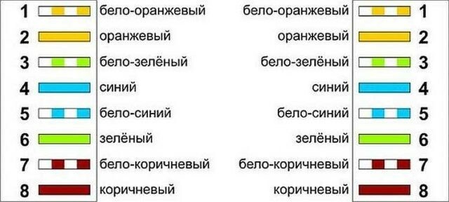
The T568A is intended for commercial (government) use. The white-green wire in this pinout is connected to the first contact, the green wire is connected to the second; white-orange, white-blue, orange, white-brown, brown - then to the third, fourth, fifth, sixth, seventh and eighth contacts in sequence.
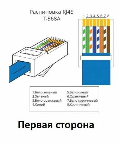
RJ45 T-568A pinout
T-568B color scheme
T568B is used in private commercial organizations (offices, trading, purchasing and manufacturing enterprises). Description of the connection diagram: white-orange wire - the first contact, orange - the second, then white-green, blue, white-blue, green, white-brown, brown - in series.
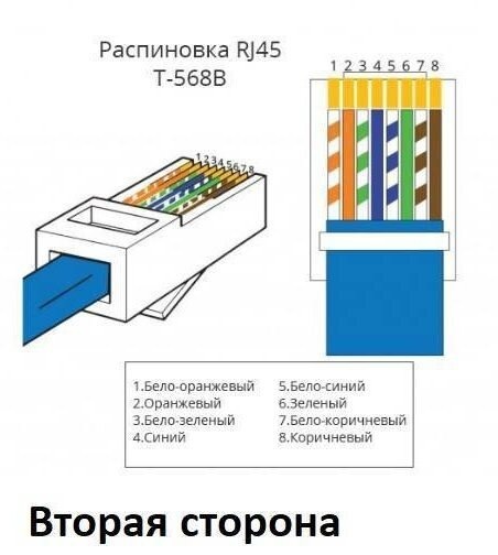
RJ45 T-568B pinout.
Selection and preparation of tools
To prepare and crimp the cable you need:
- Crimper is a tool for establishing contact (connection) between pairs of cables. Used for crimping and attaching it to connectors. Price range of the tool: from several hundred to several thousand rubles (the choice depends on the frequency of use and the required wear resistance).
- Knife. Designed for removing insulation. It must be purchased if the crimper does not have cutting edges. Most often, craftsmen opt for stationery knives with a wide blade.
- Flathead screwdriver. May be necessary during the process of fixing contacts.
- The testing device is a LAN cable tester. Necessary to determine the operability of the cable line. In the case of household crimping (working with a home network), it is enough to check the crimped cable on a working device (for example, a home PC). In this case, you can do without the device.
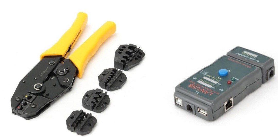
Multifunctional crimper and tester for checking LAN cable.
Preparing twisted pair for crimping
Stages:
- Choosing a crimping method. Since most modern devices have a built-in adaptation function, you can use direct pinout.
- Unsoldering and stripping of wires. It is important to disconnect the connection or remove the insulation from each contact without affecting the inner sheath of the conductor. As a single size, 1.5 pin lengths of the RJ-45 connector are taken.
- Promotion of twisted pair. The insulated part should remain unchanged (this form of cable stabilizes the voltage and helps to avoid noise interference from long lines). After this, the conductors are distributed according to the selected pinout pattern (T568B or T568A).
- Connecting the wire to the connector. For each contact there is a connector inside that does not allow them to move. During the process, it is permissible to hold the cable with your finger so as not to disrupt the connection sequence. In this case, it is necessary to retract the nylon thread to avoid getting it into the connector.
- Establishing a connection and checking functionality. After the wires reach the extreme contact points, check that the connector latch covers the insulated part.
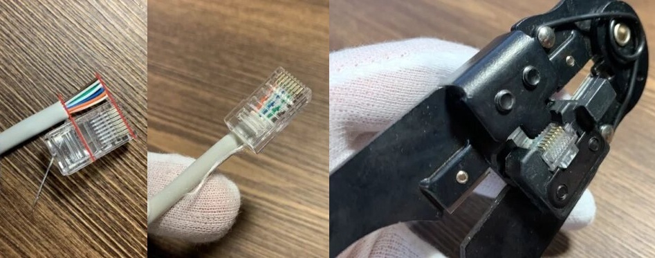
Step-by-step crimping.
RJ-45 connector pinout: diagrams and step-by-step instructions
There are 4 types of pinout: straight for 4 or 8 wires, cross for 4 or 8 wires.
Direct pinout of RJ-45 for 8 cores (568V)
With direct eight-core pinout, 4 pairs of conductive elements are used. In this case, each pin connected to a twisted pair wire has a similar number (connected to the same pin) at the other end. This connection method is typical for creating local networks. Most often used in the offices of small companies.
Direct pinout RG45 with 8 cores is suitable for connecting scanners, printers and other printing equipment; it is also used for routers or direct connection of a PC network to the Internet. The recommended length is no more than 100 m.
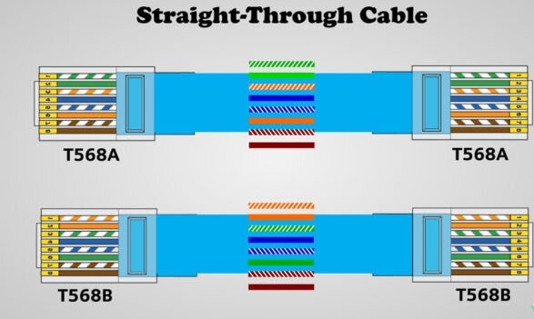
Straight 8-conductor cable.
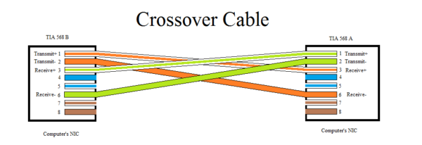
Crossover (crossover 568A) for 8 cores
The eight-core crossover pinout of the RJ-45 connector (“crossover”) is designed to connect a pair of PCs or a pair of PC – printer or PC – network storage (a very small local network). Its use allows you to avoid installing a switch and router.
With crossover pinouts, the pins at different ends intersect. That is, the wire connected to the first connector at the opposite end of the cable will connect to third, and vice versa (location of contacts in this case: 1–2 and 3–6 and 3–6 and 1–2 at the other end wires).
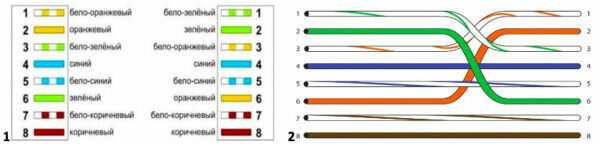
Eight-core cross pinout diagram of an RJ-45 connector.
Direct crimp "RJi"-45 with 4-core twisted pair
In addition to the eight-core pinout, a four-core cable is often used. With direct crimping, the pinout of the contacts on both ends of the wire is as follows: white-orange and orange contacts go to pins 1–2, white-green and green – to 3–6. Just as with eight-core crimping, the order of connection at the other end of the cable is preserved in this case.
Connecting a four-wire pair with direct crimping provides immunity from dynamic and noise interference on long lines. However, it has much greater resistance to electrodynamic extraneous signals.
This type of scan is used for test connections to the Internet and direct connection of computers to network devices (modem, router, switch).

4-wire connection.
Cross circuit for pumping speed 1 Gbit/s – for 4 pairs
A four-wire “crossover” (cross crimp type) is used to connect 2 or more PCs to each other. This pinout is useful when operating a local network in test mode (during setup) or directly 2 office computers (without network devices). In this case, you can use an ordinary Internet cable. In addition, the connection allows you to achieve a data transfer rate of 1 Gbit/s.
4-wire crossover.
Console cable crimping diagram (rollover cable)
This distribution scheme assumes a “mirror” connection of contacts. That is, one end of the cable is connected in a direct way, and the second in a reverse way (the first and eighth contacts are swapped, similarly: 2–7, 3–6, 4–5).
This type of connection is used for switches, routers and routers, as well as for setting up and crimping patch cords. Rollover cable is an important element of network infrastructure designed for managing local networks.

Connecting a twisted pair cable to an outlet using a connector
The process of connecting a twisted pair cable to an outlet using wiring is one of the simplest, because... The connection color scheme is printed on the contact panel.
Therefore, it is enough to arrange the wires by color and slam the socket cover. They will be fixed automatically. Older models do not have an automatic fixation system, and installation may require a joint extractor knife.
In addition, connection via a coupling is possible. This method is used to connect 2 cables to an outlet at once. In this case, the wires are connected alternately. In some cases, you can use a special RJ-45 connector consisting of 2 sockets placed in one box.
Tips to make twisted pair installation easier
You can approximately determine the length of the cable without resorting to a ruler or tape measure. The distance from the fingertips to the opposite shoulder corresponds to the ancient unit of measurement - the arshin - and is approximately equal to 1 m.
To avoid accidentally breaking the cable or breaking the contacts on the bend, it is recommended to crimp the outer shell of the connector with the input.
It is important that the exposed part of the wire completely covers the contacts. It should be inserted into the slide all the way.
Don't ignore LAN testers. They allow you to check the correct connection and functionality of the cable.
If you still have questions about cable crimping, watch the instructional video.
Published 10/27/2023 Updated 10/27/2023 by User Alexander (administrator)