When studying electronics and processes associated with it, one cannot ignore such an important concept as current resonance. In addition to electronics, this physical phenomenon has found its application in many fields, including electrical engineering and even medicine.
Since current resonance is actively used in everyday life, an understanding of its features and principles of occurrence and areas of application is necessary not only for specialists, but also for everyone who is interested in this topic and who works in related areas.
Content:
- Definition and physical meaning
- Basics of Parallel Loop Resonance
- Analysis of the phenomenon of resonance in a parallel circuit
- Formulas and calculations for resonant currents
- Comparison of parallel and series resonance
- Differences and conditions for the occurrence of parallel current resonance
- Practical Application of Series and Parallel Resonance
- Practical aspects of current resonance in a parallel oscillating circuit
- Circuit Setting Methods
- Calculation of resonant capacitance and inductance
- Areas of use
- Industry and technology applications
- Telecommunications and radio engineering
- The significance of the phenomenon for modern electronics and electrical engineering
- Conclusion
Definition and physical meaning
Current resonance is a physical phenomenon that is characterized by the current in an electrical circuit reaching its maximum value in the presence of a certain frequency of alternating current. This phenomenon is possible only in a circuit with alternating current, since the obligatory elements that cause resonance are capacitance and inductance, tuned to the same frequency.
The physical meaning of the phenomenon becomes clear when considering the energy side of the process. Resonance occurs when the energy stored in the magnetic field of the coil becomes equal to the energy of the electric field of the capacitor. In this case, the oscillations are opposite in phase, due to which energy is exchanged.

Basics of Parallel Loop Resonance
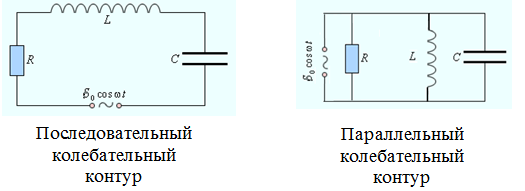
A resonance that occurs in a parallel oscillatory circuit or rlc circuit is considered parallel. A parallel circuit contains 3 main elements: r stands for resistance, l stands for inductance, and c stands for capacitance. Each element plays an important role in creating resonance.
The main condition under which the oscillatory circuit enters resonance is the creation of the equality XL = XC. In this case, the resistance of the oscillatory circuit to alternating current increases significantly, that is, a resonant resistance appears, expressed by the formula R res = L / CR.
Analysis of the phenomenon of resonance in a parallel circuit
The occurrence of resonance in a parallel circuit occurs when the voltage frequently applied to it, the inductance of the coil or the capacitance of the capacitor changes. In this case, the value of the angular frequency necessary to create resonance is determined by the formula v (0) = 1/√LC.
When certain conditions are met, the reactance is zero and the equivalent resistance is activated. In this case, the input voltage and current are in phase. This is resonance, and the presented relationship becomes the main condition for its occurrence.
Formulas and calculations for resonant currents
There are several well-known formulas for analysis and calculation, each of which is aimed at determining a specific characteristic.
Three basic formulas:
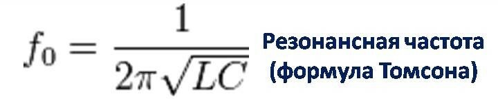
- The formula that determines the resonance frequency is fres = 1 / (2π√LC);
Here fres means the resonance frequency expressed in hertz, π is a mathematical constant equal to the value 3.14..., L is the inductance, and C is the capacitance of the electrical circuit.
- The formula for determining the amplitude of currents is Ires = Ui / (ωL);
Here Ires is the amplitude of the currents, expressed in amperes, Uya is the well voltage on the phase shifter, ω is the angular frequency (2πf), and L is the inductance.

- The formula for calculating active resistance at resonance is Ract = Uya / Ires.
Here Ract is the active resistance in ohms, Uya is the well voltage on the phase shifter, and Ires is the amplitude of the currents.

Knowledge of these formulas allows engineers and electrical specialists to design and configure electrical circuits with high precision.
Comparison of parallel and series resonance
There are two main types of current resonance - series and parallel. In the first case, a minimum resistance of the zero phase is assumed, while parallel resonance is characterized by the creation equality between the resistance of inductance and capacitance, which are opposite in direction and, accordingly, compensate each other friend.
Differences and conditions for the occurrence of parallel current resonance
The type directly depends on the connection principles. For parallel resonance of currents to occur, a parallel connection of circuit elements is necessary, and for a series one, a serial connection is required.
Parallel occurs when there is a frequency at which the reactances have minimum values. For serial, a frequency is required at which equality between the reactances is established.
Practical Application of Series and Parallel Resonance
As can be seen from what has been described, the key difference between the phenomena lies in the way the reactive elements are connected, which affects the definition of their areas of application.
Parallel resonance has found active use in current control circuits in devices and equipment with frequency control. As for series resonance, it is effectively used to create filters, as well as voltage regulators.
When choosing between parallel and series resonance, you should take into account the requirements of the system and the conditions for its effective operation. If voltage is key, then series resonance will do the job just fine. If current or frequency stability is important, then parallel resonance is suitable.
Practical aspects of current resonance in a parallel oscillating circuit
To better understand the essence of the phenomenon, we can consider it using the example of an oscillatory circuit located in an electronic circuit. Its main elements are a capacitance, a coil and an inductor connected in parallel.
Resonance is associated with the occurrence of regular oscillations of a certain frequency when the energy of the electric field of the capacitance transforms into the magnetic field of inductance. Strong resistance begins, eliminating the possibility of unimpeded passage of current.
When power is applied, the capacitor accumulates a charge equal to the rated voltage of the current source. After the source is turned off, the capacitor closes in the loop circuit, ensuring further transfer of the discharge to the coil. Passing through it, the current provokes the generation of a magnetic field, as a result of which a self-inductive force is created directed towards the current.
Circuit Setting Methods
The setup process is carried out in several stages:
- Depending on the specifics of a particular application or system, the required frequency is determined. For example, this could be the frequency of a radio station when it comes to tuning the receiver.
- The necessary circuit elements are selected, the value of which is established based on the formula for the resonant frequency and the required resistance.
- Selected elements are connected and configured. There are two main ways here - purposefully changing the inductance/capacitance values of the elements or using adjustable (variable) components.
The presented options are the main methods for tuning a circuit into resonance. After completing the setup process, it is necessary to check whether the resonant frequency meets the required parameters, as well as the stability of the circuit at the set frequency. This check is carried out using special measuring equipment.
Calculation of resonant capacitance and inductance
Capacity is calculated using the formula:
C = 1 / (4π² * L * F), where L is the inductance and F is the resonance frequency. Using the resonant capacitance formula, you can determine the required capacitance of the capacitor to achieve the resonant state of the circuit.
To calculate the inductance at the resonant frequency, the following formula is used:
L = (1 / (4π² * C * F²)), where C is the capacitance and F is the frequency.
As can be seen from the presented formulas, there is an inverse relationship between resonant capacitance and inductance. An increase in the value of one of these quantities leads to a decrease in the value of the second.
Areas of use
The application of this phenomenon can be encountered both in highly specialized areas and in everyday life.
Industry and technology applications
Parallel resonance has been widely used in industrial and technological applications. For example, in the automotive industry this phenomenon is used to create electromagnetic fields that make it possible to determine the condition of the engine and all major systems.
Based on resonance, parameters such as temperature, pressure or vibration are measured and controlled. Also, general diagnostics of systems is carried out. Resonance is used in a wide variety of filters, medical devices, and applications, among others.
Telecommunications and radio engineering
Radio receivers and transmitters operate by tuning into the desired frequencies. An oscillatory circuit is used to amplify the signal and provide information transfer. This process is possible only if the signal frequency matches the resonant frequency of the circuit, which is also used when setting up televisions and other equipment.
The significance of the phenomenon for modern electronics and electrical engineering
The use of resonance ensures the most efficient functioning of electrical/electronic devices and systems. Resonance is used to tune, amplify, and filter signals. The properties of this phenomenon make it possible to achieve maximum power and selectivity of signals in the radio range, as well as suppression of non-resonant signals.
Conclusion
Current resonance is a physical phenomenon based on the interaction of inductance and capacitance in a circuit. The choice between parallel or series resonance is made based on the system requirements and desired results. The use of resonance allows you to amplify, tune and regulate various frequencies, due to which it the phenomenon has found application in electronics, electrical engineering, aesthetic medicine, radio engineering and telecommunications.
Published 11/23/2023 Updated 11/23/2023 by User Elvira Kasimova